Farnley Junction (near Holbeck and Leeds) Accident Collision on the 5th September 1977
The Full accident report can be read here. (Department of Transport)
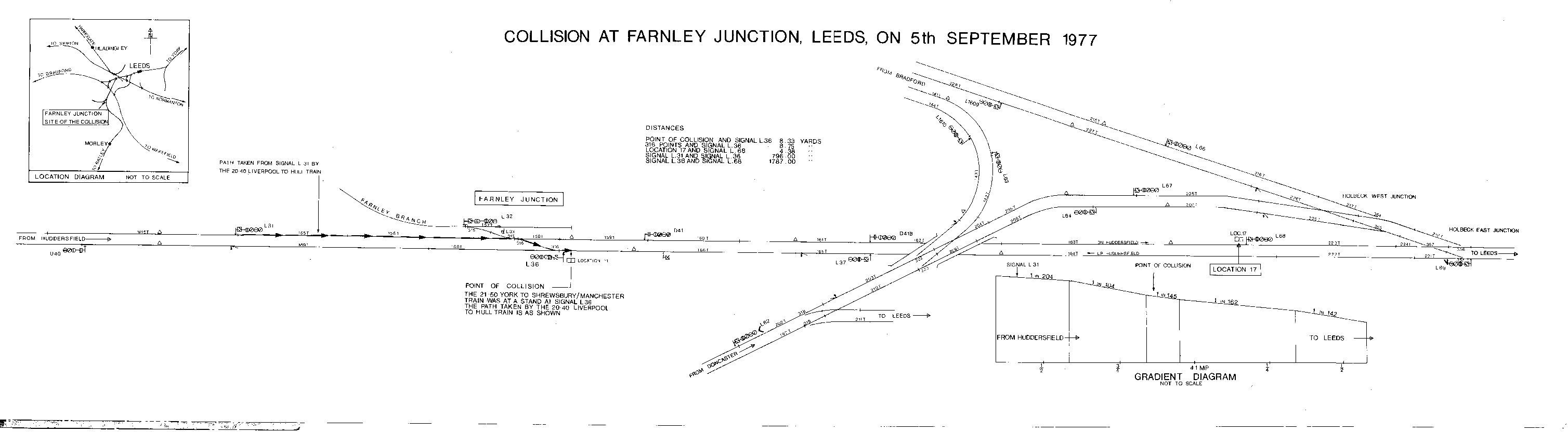
Simplified Farnley Junction track diagram at the end of this text.
The prelude to what could have been a major catastrophe was a threat of
industrial action
by power station workers of the Central Electricity Generating Board.
In 1967, a large new panel signal box had been bought into service at Leeds to
control
the remodelled station and its approaches, and it was feared the threatened
industrial action
would cause a serious voltage reduction, if not a complete shut down of the power
supply to the signal box;
and as a precaution a mobile generator had been provided and this was coupled to
the signal box during
the afternoon of 5th September 1977. One result of coupling this generator was a
slight reduction of the voltage
provided for the signalling power distribution system. The only effect of this
voltage reduction was the failure
of a number of track circuit indications on the control panel. The working of
points and signals was not affected,
and trains continued to run normally, though naturally immediate steps were
taken to restore panel indications of the track circuits.
Most of these were soon put right, but one persisted relating to track circuits
on the down line from Huddersfield,
and the fault was traced to to a transformer-rectifier set in a line side
cabinet, Location 17, near Holbeck East Junction,
just over one mile on the Leeds side of Farnley Junction, and adjacent to signal
L68 on the down line from Huddersfield.
At about 22:30, two signal technicians accompanied by a motor driver were
sent out from Leeds Signal box to location 17,
to replace the faulty transformer-rectifier set.
The signalling principles underlying the control of the equipment at Farnley
Junction must be appreciated for a clear
understanding of the causes of the accident. In the design of a very large
modern centralised interlockings,
such as Leeds, the operating convenience of having all the outlying junctions in
the approaches controlled from one large panel
has to be weighed against the cabling costs of the wiring, and the normal
economic limit for the direct control of signals and points
is about 1.5 miles. Beyond that limit it is now usual to install separate remote
interlockings, electrically connected to the main interlocking.
At Leeds there are six of these remote interlockings. At the same time
Farnley Junction, as will be appreciated from the diagram,
is so relatively small as not to justify a remote interlocking of its own, and
although roughly two miles from Leeds signal box
it is controlled direct. Because of the distance involved, and of the voltage
drop along the control cables, a relay repeater station
is provided at about the half way point. This is a line side cabinet known
as Location 17, which contains the apparatus for boosting
the control voltage, and controlling the output from a locally provided dc power
supply. It was there that the signal technicians were sent to work.
At Farnley Junction itself the industrial branch line is only used
occasionally, and the signals L31, L36, and L37 although controlled
from Leeds do not have to be reset for each move along the main line. Once
the routes have been set by pressing the appropriate
two push buttons on the Leeds control panel, they work as automatics, with
signal aspects governed by track occupation, or otherwise
of track circuit ahead. To set a route for a crossover movement to
the branch the signalman must cancel the main line routes.
The line side apparatus cabinet at Location 17 is adjacent to signal L68, on
which there is a signal post telephone
for communication with Leeds signal box.
The two signal technicians took two different varieties of
transformer-rectifier unit to site, and having arrived there the senior
of the two opened the door of the line side cabinet and studied the circuit
diagrams; he then telephoned the Leeds signal box
to tell them how changing the the transformer-rectifier unit would affect the
signals working.
He told the supervisor it would affect signal L68 beside which he was standing,
and the facing crossover points 316 at Farnley Junction.
Consequent upon the latter would also involve the signals that read over those
points. The Leeds signal box supervisor told him to go ahead,
and he then removed the fuse and disconnected the transformer-rectifier unit.
The cutting of control to the crossover points 316 was vital. At Leeds, as in
other modern installations, the relays provided for point
control and detection are a polar biased type. When the direct
current applied flows from terminal A to terminal B they are
energised to close one set of contacts, while if the polarity of flow is
reversed, from terminal B to terminal A, they close another set
of contacts. This use of polarised relays, though not of sophisticated design,
has been in operation for upwards of 70 years.
The feature is attractive in the reduced amount of cabling it permits - a major
consideration in these days of high costs in apparatus
and technology; it can be used to operate two relays over two conductors instead
of four. It is essential however, that the
dc
power supply feeding these polar biased relays is polarity correctly connected, otherwise
the relays will energise to the opposite position
required by the Leeds panel control switch.
At Location 17 the two technicians having removed the faulty rectifier found
that the smaller of the two they had brought with them was
itself a failure, and they could not get any dc output voltage from it. Then
they tried the larger one, but is was too heavy to be mounted
on the backboard of the cabinet by the small screws that were available and it
had to be placed free standing on the floor. All this was taking time.
The Leeds panel box supervisor in authorising the senior of the two technicians
had heard him say that it would only take two or three
minutes to put in a new rectifier unit; and taking a less optimistic view , that it
would probably take about 10 minutes, he had judged
that there had been time for the job to be done at once without unduly delaying
two trains shortly due to pass
Farnley Junction, one in each direction.
In the meantime the removal of the fuse and consequent disconnecting of the
control on the crossover points 316 at Farnley Junction
had put signals L31 on the down line, and L36 on the up line, both to red.; and
while the work at Location 17 was prolonged
the two trains had arrived and detained by each respective red signal.
These trains were the 20:40 Liverpool Lime Street to Hull (1E89) , a four car
diesel multiple unit class 124 E51959 , and the 21:50 York to Shrewsbury
(1M41) ,
Aberystwyth mail, hauled by class
47 402
diesel electric locomotive
and consisting
of two T.P.O. sorting carriages and eight other vehicles.
Both train drivers reported their presence at the signals concerned to Leeds signal box, and were told that there is a signal failure which it was expected would be cleared in a few minutes.
At location 17, instead of a straight substitution of one
transformer-rectifier unit for another, the fact of the replacement unit having
to be mounted on the cabinet floor made it necessary to prepare new and longer
dc output connecting leads. This was done and connections
made and the senior technician replaced the fuse. There were then
unfortunately some basic inconsistencies between the evidence
given subsequently by the technicians at Location 17 and those in the Leeds
signal box as to telephone calls between them,
while at the critical time the driver's assistant on the Shrewsbury mail,
himself a fully qualified driver, was down in the 'six foot'
trying to telephone Leeds signal box himself.
What precisely happened, in what order, around 23:10 will never be known in
any certainty; but what is a fact is that the
technicians at Location 17 in connecting up the new extended leads to the
transformer-rectifier unit had transposed the polarity
of
the two direct current leads. After the fuse had been replaced, the men in
the signal box claim, and the technicians deny,
that a telephone call was received as saying "We have finished, it is in order".
After this had been reported to the supervisor,
and the faulty track circuit indications on the panel seen to be restored,
instructions were given to press the appropriate
buttons to restore automatic signal working at Farnley Junction. At this very moment the driver's
assistant on the mail train was still trying to telephone
the Leeds signal box, and down in the 'six-foot' he was surprised to hear
the electro pneumatic points just ahead of him move from normal
to reverse crossover movement, and immediately afterwards the signal at which
they had been detained change from red to green.
With the points set set for a crossover movement to lead onto
the branch, he was surprised to see a green aspect
instead of the usual subsidiary yellow with the route indictor to the branch. He
realised this was irregular,
but had assumed it was something to do with the technical faults reported to him
when he had first telephoned the signal box.
He spoke to his driver, who also heard the points moving, and then went to try
telephoning the signalman again.
What had happened of course was that the polarity transposition of those 'new
longer leads'
at Location 17 had caused the points to reverse,
and the detection also, with the appalling result that the signals had cleared
for the straight ahead route while the points had
moved into reverse crossover position. Signals L31 and L36 were
set for a collision course over points 316, and this is what actually happened.
While those drivers on the mail train were near to the points and realising something
was wrong did not move, the Hull train,
which had been detained at signal L31, had no premonition of danger.
It was 700 yards away from the fatal points,
and directly seeing signal L31 cleared to green, its driver started straight
away. On the falling gradient first 1 in 204
then 1 in 104 the train accelerated rapidly. In the darkness, and with no
signal in the vicinity that would shine reflectively on the line
points at Farnley Junction,
there was no chance of the driver seeing that the points were set incorrectly for the
crossover, until, at a speed of 40 mph
the train suddenly swerved to the right; and although a full emergency
application of the brakes was made, at about 30 mph
the DMU collided head on with the standing mail train. The drivers of both
trains were killed, he of the mail train instantly while
the other of the DMU a few hours later. Only nine passengers were injured, none of them
seriously.
Addendum:-
Normal logic, e.g., for signals,
is binary, but the controls and position
detection of the up-to-down-line at Farnley Junction crossover happened to be trinary,
2 wire
control cable (wire A positive = straight ahead, wire B positive = cross over, neither
wire positive = no command / not correctly set).
On the day in question, a fault at the repeater unit ( line side cabinet 17 at
Holbeck East Junction) was causing problems.
Both signals were set to Danger by the signalman, and an engineering team
then changed the rectifier / power supply at the repeater unit.
The loss of power caused the main signalling logic to believe the crossover
was not correctly set (no repeat of the detection), and so it set the control
lines to drive the crossover points back to the straight ahead position (this will
stay driven until the detection is correct - meantime, both signals L31 and L36 are locked
at Danger).
Both the DMU and mail trains came to a halt and detained at both signals.
The engineers restored power to the repeater, but had wired in the rectifier
dc output
the wrong way round. This had the effect of reversing the polarity of voltages
repeated - not important for binary signals. The crossover logic took the
incoming
voltage polarity as a command move to the "crossover" or "reverse" position
(positive on wire B), and did so.
The detection mechanism correctly reported "crossover" to the
interlock logic - - this logic was reversed
at the repeater cabinet 17 (due to incorrect wired voltage polarity from the
rectifier unit),
and the main signalling logic (correctly) took the incoming dc
signal to mean that the points were locked in the "straight ahead" position.
The signalman now set both signals to Proceed, and the signalling logic (now wired incorrectly)
allowed him to do so. The train on the Up line (650 yards away from points 316) started off immediately
on observing the detaining signal L31 change to a green aspect.
The other driver at signal L36 and facing crossover points 316 was trying to figure out why the facing points had moved for a
crossover movement
onto the branch which were immediately ahead of him (the driver was still trying
to contact the signal box by telephone as he observed this)
and the protecting signal L36 changed to green with the route indicatotor the branch
extinguished.
The oncoming accellerating DMU train unaware of the imminent danger ahead traversed the crossover, and collided with the
mail train waiting on the down line at signal L36.
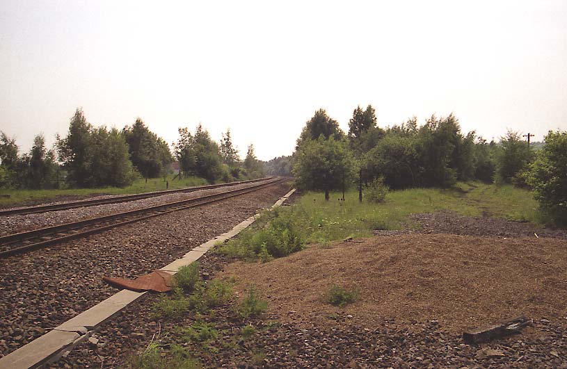
At the time of my writing this (2005), Farnley Junction industrial branch has long since been
lifted and removed.
The junction once served a branch line about a mile long to a large steel
stockist, Iron Co. Works later named Dunlop and Rankin,
and to Farnley Fireclay.
Here is a photo of the location where Farnley Junction industrial branch used to be (looking South):-
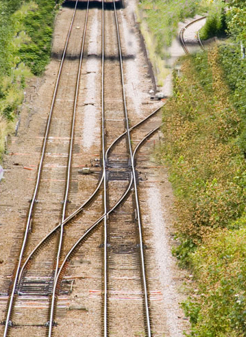
Below is a picture similar to that which existed at Farnley Junction industrial branch
to Dunlop and Rankin also Farnley Fireclay
.
Image is not of Farnley Junction but shows a similar facing crossover
and junction turn out similar to points 316 which were reversed causing the accident.
Google Map image - You can see where the industrial branch line used to be.
Shown here is a typical modern day transformer-rectifier unit.
This is not the actual
design used at Farnley Junction repeater cabinet 17.
![]()
This relay is to design specification QBA1 as typically used at Farnley Junction (1977--Lineside cabinet 17).

QBA1 |
Characteristics: This style of relay is a miniature, dc biased, ac immune. tractive armature, line relay. It is designed for railway signalling purposes where alternating currents at industrial frequencies (50Hz) may be present and where the relay operation is dependant on the polarity of the coil current. The contacts are Silver impregnated Graphite to Silver (SIG/Sil). The relay conforms to BRB Spec 932A. Approximate weight : 1.3 kg
|
Nominal Working volts |
Contacts |
Coil resitance (ohms) |
Max full operating volts |
Min Release volts |
Interlocking |
50 |
8F 8B |
920 |
40 |
7.5 |
ACDGH (028) |